Industry Solutions
Industrial Effluent Treatment Plant Process Design
Practical guide to industrial ETP process design, covering wastewater characterization, chemical treatment, DAF, biological treatment, reuse and sludge dewatering.
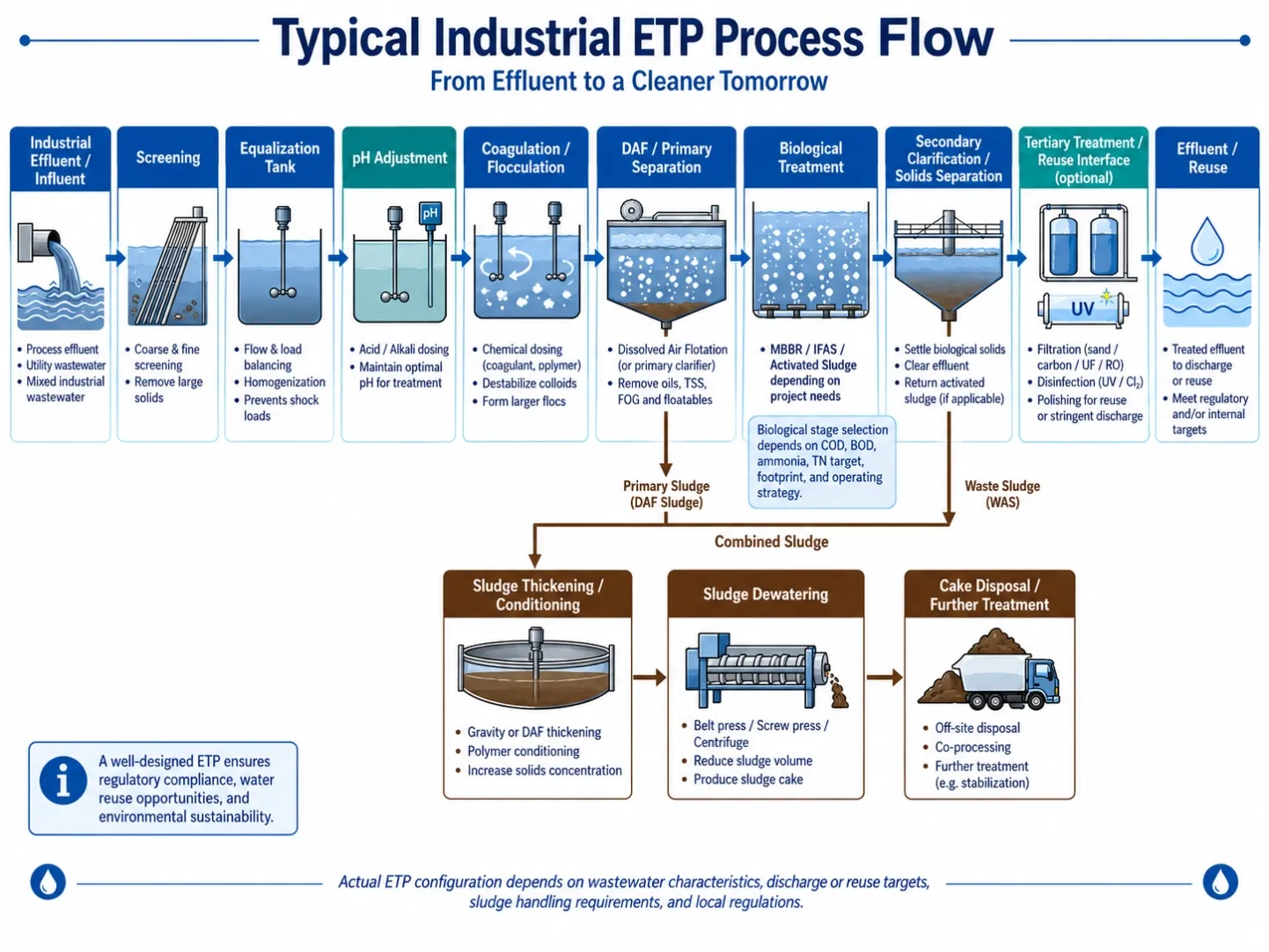
An industrial effluent treatment plant should not be designed as a collection of individual machines.
The starting point is the wastewater itself: where it comes from, how much the flow varies during production, which contaminants are present, and what the treated water must achieve before discharge or reuse.
Only after these conditions are understood should the treatment train be defined.
For many industrial plants, the final process may include equalization, pH adjustment, chemical treatment, solids separation, biological treatment, tertiary polishing and sludge dewatering. But the sequence—and the size of each unit—depends on the wastewater characteristics.
This is why two factories with the same wastewater flow can require very different ETP designs.
A useful engineering approach is:
Wastewater characterization → process selection → equipment sizing → sludge handling → control and integration
—not equipment selection first.
Start with Wastewater Characterization
Flow rate is important, but it is not enough to design an industrial ETP.
Before defining an ETP process flow, engineers normally need to understand both hydraulic loading and pollutant loading.
At a minimum, the design basis should consider:
- average and peak flow
- operating hours per day
- pH range
- COD and BOD
- suspended solids
- oil and grease
- temperature
- ammonia and total nitrogen where relevant
- phosphorus
- salinity or conductivity
- metals or specific industrial contaminants
- daily or seasonal fluctuations
- discharge or reuse limits
The source of each wastewater stream also matters.
For example, relatively clean cooling water, high-COD process wastewater and concentrated cleaning wastewater should not automatically be mixed before their characteristics are evaluated.
Segregating certain streams may reduce the load on the main treatment plant or allow a more targeted treatment step.
For plants with strong batch discharges, equalization can be just as important as the downstream treatment equipment. A biological reactor designed around an average COD value may perform poorly if it receives short periods of very high organic or chemical loading.
The design basis should therefore describe not only the average wastewater condition, but also the expected variation.
Build the Complete Industrial ETP Treatment Train
There is no single standard ETP process that fits every industrial wastewater stream.
A typical treatment train may look like this:
Screening / collection → equalization → pH adjustment → chemical treatment → solids separation → biological treatment → tertiary polishing → discharge or reuse
At the same time, a separate sludge line must be considered:
Primary sludge / biological sludge → thickening or conditioning → dewatering → cake handling or further treatment
The two lines should be designed together.
Equalization and pH Control
Equalization provides a buffer between production and the treatment process.
Its job is not simply to store wastewater. A properly designed equalization stage can reduce fluctuations in:
- flow
- pH
- temperature
- COD concentration
- suspended solids
- chemical load
Mixing is normally required to prevent settling and maintain a reasonably uniform feed to downstream treatment.
Where wastewater pH varies significantly, acid or alkali dosing may be required before coagulation, biological treatment or other sensitive processes.
The dosing system should be selected according to actual chemical consumption, storage requirements, automation level and control philosophy.
A dosing pump should not be sized only from the pipe diameter or wastewater flow. The required dose and expected concentration range need to be established first.
Chemical Treatment and DAF
Industrial wastewater containing suspended solids, emulsified oil, fats, colloidal material or certain precipitable contaminants often requires chemical treatment before biological treatment.
The typical sequence may include:
pH adjustment → coagulation → flocculation → solid-liquid separation
Chemical treatment changes contaminants into a form that can be separated more effectively.
Depending on the wastewater, separation may then be carried out through sedimentation or dissolved air flotation.
A dissolved air flotation system is particularly useful where the solids have poor settling characteristics or where wastewater contains oil, grease or light floc.
However, DAF performance depends heavily on what happens upstream.
Coagulant selection, polymer type, dose, pH and floc formation can have as much influence on separation as the flotation equipment itself.
For an EPC evaluating DAF equipment, useful design information includes:
- design flow and peak flow
- influent TSS
- oil and grease
- expected chemical program
- solids loading
- wastewater temperature
- required effluent quality
DAF should therefore be considered part of a chemical separation process, rather than a stand-alone machine expected to solve every suspended-solids problem.
Biological Treatment
After unsuitable solids, oil or inhibitory contaminants have been reduced, biological treatment can address biodegradable organic matter and, where required, nitrogen compounds.
Possible processes include activated sludge, MBBR, IFAS and other attached-growth or suspended-growth systems.
The correct process depends on the required treatment objective.
For example, removing bulk biodegradable COD is not the same design problem as achieving reliable nitrification.
Important biological design inputs can include:
- biodegradable COD or BOD loading
- ammonia load
- required nitrogen limits
- wastewater temperature
- pH and alkalinity
- dissolved oxygen requirement
- inhibitory compounds
- available reactor volume
- hydraulic retention time
Aeration and biological treatment should also be considered together.
Airflow requirements should be based on oxygen demand and mixing requirements rather than simply selecting a diffuser quantity from tank volume.
Fine-bubble disc or tube diffusers may be used in biological tanks depending on tank geometry, operating conditions and maintenance strategy.
Tertiary Treatment and Reuse Interface
Biological treatment is not always the final step.
Where discharge requirements are tighter, or where treated water will be reused, additional polishing may be required.
Depending on the application, this can include:
- clarification
- filtration
- nutrient polishing
- activated carbon
- membrane treatment
- disinfection
- advanced oxidation
The important question is not simply:
“Can we add a tertiary unit?”
The better question is:
“What is the quality of the water entering that unit?”
For example, membrane equipment placed downstream of unstable suspended-solids removal may experience unnecessary fouling. Similarly, a reuse system cannot compensate economically for poor upstream oil or solids removal.
The treatment stages should therefore be designed as a sequence, with each unit producing water suitable for the next.
Sludge Thickening, Dewatering and Further Treatment
Sludge handling is frequently treated as an afterthought in industrial ETP projects.
That is a mistake.
Chemical treatment generates sludge. Biological treatment generates excess biomass. DAF generates floated solids. All of this material eventually has to be removed from the plant.
A complete design should estimate:
- sludge source
- expected dry-solids mass
- feed solids concentration
- operating hours
- polymer requirement
- target cake condition
- filtrate or centrate return
- final disposal route
The correct equipment depends on what the project actually needs.
If the objective is only to increase sludge concentration before another process, the requirement is thickening.
If the objective is to produce a handleable cake and substantially reduce the water content before transport or disposal, the requirement is dewatering.
Equipment such as a volute screw press, belt filter press or chamber filter press should therefore be selected according to sludge characteristics and the required final condition—not simply because one machine has a higher nominal flow rate.
Polymer preparation and dosing also forms part of the dewatering system. Poor polymer preparation can reduce floc strength and affect downstream dewatering performance.
How Each Treatment Stage Affects the Next
One of the most important principles in industrial wastewater treatment is that equipment cannot be evaluated in isolation.
Consider a few common examples.
If equalization is undersized, the chemical treatment stage may receive unstable pollutant loading.
If coagulation and flocculation are poorly controlled, the DAF may carry excessive suspended solids into biological treatment.
If oil is not adequately removed upstream, it may interfere with biological treatment or downstream filtration.
If biological solids separation is unstable, tertiary filtration may foul more quickly.
If sludge dewatering filtrate contains a significant pollutant load and is returned to the head of the plant, that recycle stream becomes part of the ETP mass balance.
A well-designed plant therefore looks at interfaces between units, not only the performance of each machine.
That is one of the main differences between equipment supply and process integration.
When MBBR or IFAS May Be Suitable
MBBR and IFAS are often considered when an industrial plant requires more biological treatment capacity without a large increase in tank volume.
They may be worth evaluating where:
- an existing biological system requires additional capacity
- nitrification capacity is insufficient
- wastewater loading fluctuates
- available reactor footprint is limited
- an existing activated sludge plant is being upgraded
- additional attached biomass would improve process resilience
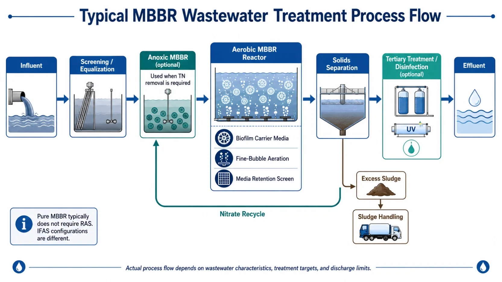
MBBR uses suspended biofilm carriers as the primary support for attached biomass.
IFAS combines attached-growth media with suspended activated sludge.
Neither process should be selected solely because bio-media has a high specific surface area.
The engineering evaluation still needs to consider organic loading, ammonia loading, oxygen demand, temperature, alkalinity, hydraulic conditions, media retention and the characteristics of the wastewater entering the biological stage.
For retrofit projects in particular, the existing tank volume, aeration system and solids separation capacity should be reviewed before deciding how much carrier media to install.
Equipment Information Required by EPCs
Equipment suppliers can usually provide a more useful technical proposal when the process basis is clear.
For industrial ETP projects, the following information is particularly useful.
Project data
- industry and wastewater source
- installation location
- new plant or retrofit
- operating hours
- available footprint
Hydraulic data
- average flow
- peak flow
- daily volume
- batch discharge conditions
Water quality
- COD
- BOD
- TSS
- oil and grease
- pH
- temperature
- nitrogen
- phosphorus
- salinity
- relevant metals or process chemicals
Treatment objective
- local discharge standard
- client-specific discharge limit
- reuse application
- target parameters
Sludge requirements
- sludge source
- feed concentration
- estimated sludge volume or dry-solids load
- desired cake condition
- disposal method
With this information, equipment selection can move from a catalogue exercise to an engineering discussion.
Common ETP Integration Mistakes
Several problems appear repeatedly in industrial wastewater projects.
Selecting equipment from flow rate alone
Two wastewater streams at 100 m³/day can have completely different solids, oil, COD and nitrogen loads. Hydraulic capacity alone does not define the treatment duty.
Underestimating peak loads
Average laboratory results may hide batch discharges or production peaks that affect chemical dosing and biological stability.
Expecting one treatment unit to remove everything
DAF, MBBR, filtration and sludge presses solve different treatment problems. Adding more equipment does not replace a clear process sequence.
Ignoring the effect of chemicals on biological treatment
Changes in pH, residual chemicals, salinity or toxic compounds can affect biological performance downstream.
Designing the water line but not the sludge line
Every solids-removal process transfers contaminants from water into sludge. The sludge has to go somewhere.
Specifying reuse without defining the reuse requirement
Cooling water, process washing and high-purity reuse do not require the same treated-water quality. The reuse objective should be defined before selecting tertiary treatment.
Submit Your Wastewater Data
A useful ETP proposal starts with project data rather than an equipment list.
For preliminary process and equipment evaluation, send HydroNovus:
- wastewater source and industry
- average and peak flow
- available water analysis
- discharge or reuse target
- current treatment process, if this is a retrofit
- available footprint
- sludge handling requirement
Based on this information, the treatment train can be reviewed stage by stage—from pretreatment and chemical separation to biological treatment, aeration and sludge dewatering.
Submit your wastewater data for preliminary process review.